UML (Unified Modeling Language) has expanded its roots in the fields of design and visualization. There is much to offer in this area to potential searchers and people interested in visualizing software engineering. This complete set of Java UML interview questions contains the most accurate answers to help you with this topic. These questions will guide you thoroughly to acquire a modeling language platform in a particular area of software development.
Presents the most useful UML interview questions that provide enough information for job interviews. UML typically contains a complete graphic representation of the technique used to create a visualization of a software-intensive system and its objects. Below is a list of the best questions and answers for UML interviews.

1. Explain Deployment Diagram?
- Software components are used to describe the hardware components in which they are deployed.
- Component diagrams are used to describe the components, and layout diagrams show how they are deployed in hardware.
- Deployment diagrams consist of nodes.
- Nodes are nothing but physical hardware used to deploy the application.
- Describe the physical components and their distribution and association
2. Explain the Use Case diagram?
- Capture the dynamic aspects of a system.
- Used to capture system requirements, including internal and external influences, to capture the dynamic aspects of the system.
- These requirements are primarily designed requirements.
- For the system to collect its functionality When analyzed in, use cases are prepared and actors are identified.
- Use cases are just system features written in an organized way.
3. Explain the Interaction Diagram?
- Describe some types of interactions among the different elements in the model.
- This interaction is part of the dynamic behavior of the system.
- Sequence diagrams and collaboration diagrams are used in UML for this purpose.
- Sequence Diagram – Emphasizes time sequences of messages.
- Collaboration Diagram – Emphasis on the structural organization of objects that send and receive messages So the following things are to be identified clearly before drawing the interaction diagram:
- Objects taking part in the interaction.
- Message flows among the objects.
- The sequence in which the messages are flowing.
- Object organization.
- The message flow is nothing but a method call of an object.
- In the collaboration diagram, the method call sequence is indicated by some numbering technique
- The difference is that the sequence diagram does not describe the object organization whereas the collaboration diagram shows the object organization.
- If the time sequence is important then a sequence diagram is used and if the organization is required then a collaboration diagram is used.
4. Explain the StateChart diagram?
- Describes various states of components (objects) in the system.
- These states are controlled by internal or external events.
- Used to model the dynamic nature of the system.
- Finally, we need to Clarify the states Before drawing the StateChart diagram:
- First, Identify important objects to be analyzed.
- Secondly, Identify the states.
- Finally, Identify the events.
5. Explain the activity diagram?
- Basically, a flow chart showing the flow from one activity to another.
- The activity can be represented as an operation of the system.
- This flow can be sequential, branched, or simultaneous.
- Other diagrams are used to represent a message show Flow from one object to another.
- However, the activity is used to show the flow of control from one activity to another activity.
- Activity is a particular operation of the system.
- Before you can create an activity diagram, you need to identify the following elements:
- Activities
- Association
- Conditions
- Constraints
6. What is modeling? What are the advantages of creating a model?
- Modeling is a proven and recognized technique that helps you create models.
- The model is a simplification of reality.
- All you need to build is a blueprint for the actual system.
- Benefits of using this model:
- First, it helps you visualize the system.
- Second, it helps you specify the structure and behavior of your system.
- Third, it helps you create templates for building your system.
- Finally, it helps document the system.
7. What is SDLC?
- SDLC is the life cycle of software development.
- The SDLC of the system included the use case-oriented, architecture-centric, iterative, and incremental processes.
- This life cycle is divided into phases.
- A phase is a period between two milestones.
- Milestones are start, refinement, construction, and transition.
- The process workflows that evolve through these stages are business modeling, requirements collection, analysis and design, implementation, testing, and deployment.
- Supported workflows are configuration and change management, and project management.
8. What are Relationships?
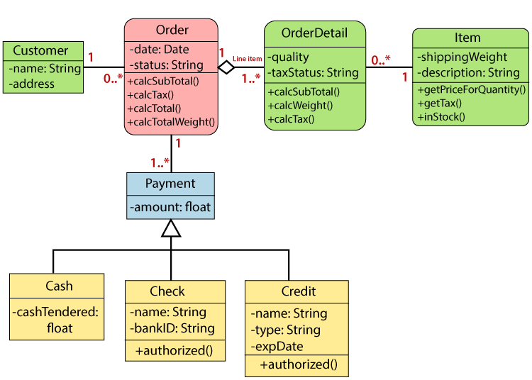
- There are different types of relationships, such as dependencies, generalizations, and associations.
- Dependencies are relationships between two entities whose specification changes can affect another.
- Most commonly used to indicate that one class receives another as an argument to the operation’s signature.
- Generalization is the relationship specified in the class-subclass scenario.
- These are displayed when one entity inherits from another.
- Associations are structural relationships such as The room has walls and people work for the company.
- Aggregations are the types of associations that are related.
- That is, if a room has walls, two classrooms, and walls, the relationship is called an association and is further defined as an aggregation.
9. Can I name different elements of the collaboration diagram?
Collaborative diagrams basically have three types of elements they are:
- Objects :
- Interactions within the system always occur between two objects.
- Objects are always represented by a rectangle with the object’s name. Before that is a colon and an underscore.
- Relationships :
- Also known as associations, they always belong to the object linked to the connection in the system.
- They are represented by placing qualifiers at both ends.
- Message :
- An instance of communication from one point to another important point or destination is a message.
- It always maps the interactions provided between objects in the system.
- The order of this interaction is indicated directly by number.
10. What elements are used in the activity diagram?
The main elements used in the activity diagram are:
- Activity:
- Indicates the action that needs to be performed or has been performed on the system.
- Transition:
- Represented by an arrow and used to indicate the bottom that occurs between the elements of the chart.
- Decision Point:
- In the system, the logical branch is highlighted by the decision point.
- States:
- These are shown to refer to milestones for processing activity diagrams and are represented by rounded rectangles.
